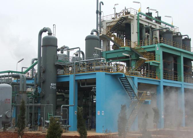
Chlor Alkali Plant

chlor alkali plant
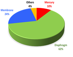
The chlor-alkali (also called “chlorine-caustic”) industry is one of the largest electrochemical technologies in the world. It is an energy intensive process and is the second largest consumer of electricity (2400 billion kWh) among electrolytic industries. In 2006, about 84% of the total world chlorine capacity of about 59 million metric tons was produced electrolytically using diaphragm and membrane cells, while about 13% was made using mercury cells.

Chlorine is produced by the electrolysis of sodium chloride (common table salt) solution, often called “brine.” Thus, when sodium chloride is dissolved in water, it dissociates into sodium cations and chloride anions.

The chloride ions are oxidized at the anode to form chlorine gas, water molecules are reduced at the cathode to form hydroxyl anions and hydrogen gas. The sodium ions in the solution and the hydroxyl ions produced at the cathode constitute the components of sodium hydroxide formed during the electrolysis of sodium chloride.

There are 3 types of electrolytic cells to produce chlorine. The main difference in these 3 technologies lies in the manner by which the chlorine gas and the sodium hydroxide is prevented from mixing with each other to ensure the purity of the products. Thus, in diaphragm cells, brine from the anode compartment flows through the separator to the cathode compartment, the separator material being either asbestos or polymer-modified asbestos composite deposited on a for aminous cathode.

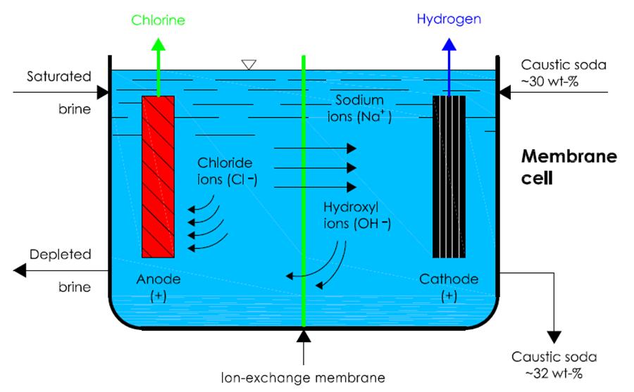
On the other hand, there is an ion-exchange membrane in membrane cells is used as a separator. Anolyte-catholyte separation is achieved in the diaphragm and membrane cells using separators and ion-exchange membranes, respectively, whereas mercury cells contain no diaphragm or membrane and the mercury itself acts as a separator. The anode in all technologies is titanium metal coated with an electrocatalytic layer of mixed oxides.

A membrane cell is a diaphragm cell with an improved diaphragm called a ‘membrane’. This is made from polytetrafluoroethylene (PTFE), making it a plastic membrane, which has been modified to include anionic groups to act as an ion exchange membrane. This allows sodium ions to pass through it but not chloride or hydroxide ions. PTFE is very inert and so can stand immersion in hydroxide solutions for long periods of time. Therefore, the same reactions occur as above in the diaphragm cell but there is no by-product of sodium chloride due to the membrane preventing the chloride and hydroxide ions to pass through.

The use of this process results in virtually pure sodium hydroxide (only contains about 0.02% of sodium chloride at most) being produced as there is no contamination by chloride, and there is virtually no oxidant in the spent brine. Furthermore, there is no working hazard of working with asbestos or mercury.

This process of using electrolysis to develop sodium hydroxide, has been adapted in all chlor-alkali plants due to its very pure production of sodium hydroxide, similar costs to that of the diaphragm cell (reasonable) and it has no negligible environmental impact. The advantages are much preferable to that of the mercury and diaphragm process and the membrane process have negligible disadvantages proving to be the best technique for extracting sodium hydroxide.

Synopsis Chemitech developed the process based on membrane electrolysis as the caustic soda plant has been adapted in all Chlor-alkali industry.

We built many caustic soda plants and potassium hydroxide plants based on our own chlor alkali process. Potassium Hydroxide solution or caustic potash is an extremely versatile cleaning agent. It is highly basic, forming strongly alkaline solutions in water and other polar solvents.

In order to make right Potassium hydroxide solutions for our clients, Synopsis Chemitech is able switch to the new technology for both chlor alkali process and membrane electrolysers. these new chlor alkali process develop by us has been satisfied by our clients and upgrading for the existing new membrane electrolysers are necessaries.

Chlor-Alkali Manufacturing Processes By Synopsis Chemitech

Electrochemical & chemical reactions occurring in diaphragm & membrane cells
[1] 2Cl- → Cl2 + 2e- (Anodic reaction)
[6] 2H2O + 2e- → 2OH- + H2 (Cathodic reaction)
[7] 2Cl- + 2H2O → Cl2 + H2 + 2OH- (Overall ionic reaction)
[5] 2NaCl + 2H2O → Cl2 + 2NaOH + H2 (Overall reaction)
[8] Cl2 + 2NaOH → NaOCl + NaCl + H2O (Side reaction)
[9] 3NaOCl → NaClO3 + 2NaCl (Side reaction)
Reaction [9] will contaminate the caustic product with chlorate.

Chemical reactions occurring in brine processing
[10] CaSO4 + Na2CO3 → CaCO3 + NaSO4(CaCO3 precipitates)
[11] MgCl2 + 2NaOH → Mg(OH)2 + 2NaCl(Mg(OH)2 precipitates)

Sodium Hypochlorite/Chlorate Manufacturing Process
Electrochemical and chemical reactions occurring in cells
[1] 2Cl- → Cl2 + 2e-(Anodic reaction)
[7] 2H2O + 2e- → 2OH- + H2(Cathodic reaction)
[8] Cl2 + 2OH- → OCl- + Cl- + H2O(Hypochlorite formation)
[9] 3OCl- → ClO3- + 2Cl-(Chlorate formation)
[12] NaCl + H2O → NaOCl + H2(Overall hypochlorite reaction)
[13] NaCl + 3H2O → NaClO3 + 3H2(Overall chlorate reaction)
[14] 3Cl2 + 6NaOH → NaClO3 + 5NaCl + 3H2O(Chemical chlorate formation)

  • Sodium Hydroxide Crystal

  • Caustic Soda Lye

  • Caustic Soda Flakes

  • Caustic Soda Pearl

Hypochlorite formation is promoted by using weak brine, basic solution, and low cell temperatures. Chlorate formation is promoted by using saturated brine, acidic solution, and temperatures close to the boiling point of the solution. For more information, please send email to info@synopsischemitech.com

Synopsis Chemitech can provide the engineering solution to the client with a highly efficient design which has the optimized process and maximum throughput. With this optimized solution, it provides a huge amount of saving in the energy consumptions which in turn leads to a much lower operating cost.

The energy consumption in chlor-alkali production originates from four main processes
1. Energy to prepare and purify the raw materials, mainly the salt (sodium chloride or potassium chloride).
2. Electrical energy used for the electrolysis process itself.
3. Energy (steam) to obtain the caustic soda (or potash) at its commercial concentration.
4. Energy for auxiliary equipment such as heating devices, pumps, compressors, transformers, rectifiers and lighting.

Energy consumption depends on several factors such as:
1. The cell technique used;
2. The purity of the salt used as raw material;
3. The specific cell parameters, such as nominal current density, anode/cathode gap, adherence of developed gas bubbles on electrode structures, diaphragm/membrane type and thickness, catalytic electrode coatings;
4. The age of the diaphragm, the membrane and the catalytic electrode coatings;
5. Other technical characteristics of the installation such as the configuration of the electrolysers (monopolar or bipolar), the number of evaporative stages in the caustic concentration unit and the chlorine liquefaction conditions;
6. The actual current density.

chlor alkali plant

Energy consumption for the electrolysis

The operation of a chlor-alkali plant is dependent on the availability of huge quantities of direct current (DC) electric power, which is usually obtained from a high voltage source of alternating current (AC).

The lower voltage required for an electrolyser circuit is produced by a series of stepdown transformers. Silicon diode or thyristor rectifiers convert the alternating current electricity to direct current for electrolysis.

Direct current is distributed to the individual cells of the electrolysers via busbars. There are energy losses across the transformer, the rectification equipment and the busbars. In 2010, the efficiency of rectifier and transformer units varied from approximately 94% (older units) to 98%. To remove the dissipated heat, the units are cooled by circulated air or by special water Circuits.

Connections between cells/electrolysers, along with the corresponding energy losses, must be considered for the measurement of the total energy requirement per tonne of chlorine produced. The definition of the exact measurement point is necessary for an appropriate comparison of energy consumption figures of different plants.

For the usual operating conditions, the specific electricity consumption w (in kWh/t Cl2 produced), which is the electricity consumed divided by the production rate, is proportional to the cell current density j (in kA/m2)

Energy consumption of membrane cells

The electrical energy consumption ranges of membrane cells from approximately 2300 to 3000 AC kWh/t Cl2 produced, the median being approximately 2600 AC kWh/t Cl2 produced, with current densities ranging from 1.0 to 6.5 kA/m2. All electrolysers are equipped with titanium anodes coated with a catalyst, and the nickel cathodes are usually activated with a catalyst to improve the terms U0 and K, and so consequently reduce the energy consumption. For non-activated cathodes, U0 is approximately the same for all units and is similar to the diaphragm electrolysers; it has lower value if the cathode is activated, but it also depending on the type of catalyst used. Compared to the diaphragm cells, the factor K of membrane cells has lower value due to a thinner separator (the membrane), a shorter distance between anode and cathode, and due to a lower electric resistance in the electrolyser structure (0.1–0.3 V·m2/kA)

The operating conditions and electrical energy consumption of mono-polar and bipolar electrolysers are different. For mono-polar membrane cells, the electrical energy consumption ranges from approximately 2700 to 3000 AC kWh/t Cl2 produced, the median being approximately 2800 AC kWh/t Cl2 produced, with current densities ranging from 1.0 to 4.0 kA/m2. For bipolar membrane cells, the electrical energy consumption ranges from approximately 2300 to 2900 AC kWh/t Cl2 produced, the median being approximately 2500 AC kWh/t Cl2 produced, with current densities ranging from 1.4 to 6.5 kA/m2. Within both techniques, there are differences in the design distance of the cathode to the membrane. These differences vary from 0 to almost 2 mm. This distance significantly affects the energy consumption (the shorter the distance the lower the energy requirement), as well as the operational requirements, such as brine purity, and the risk of membrane damage. The electrical energy consumption of a membrane cell rises with the lifetime of the membranes and the electrodes (coating ageing), by approximately 3–4% during a period of three years.

Comparison of cell technologies

MERCURYDIAPHRAGM MEMBRANE
Operating current density (kA/m2) 8 – 13 0.9 – 2.6 3 – 6
Cell voltage (V) 3.9 – 4.2 2.9 – 3.53.0 – 3.6
NaOH strength (wt%) 50 1233 – 35
Energy consumption (kWh/MT Cl2) at a current density of (kA/m2) 3360 (10) 2720 (1.7)2650 (5)
Steam consumption (kWh/MT Cl2) for concentration to 50% NaOH 0 610180

Further Enhance Solution

Synopsis Chemitech provides engineering solution to further development of the basic products into various downstream products as below:

• Caustic Soda Lye, (Flakes, Pearl)
• Liquid Chlorine Gas
• Potassium Hydroxide (KOH)
• Hydrochloride Acid (HCL)
• Sodium Hypochlorite (NaOCl)
• PVC/CPVC
• Polyurethanes
• Polyester (Polyester Film, PET Resin, Polyester Fiber, Polypropylene Fiber)
• Epoxy Resins
• Polycarbonate
• Acrylic Fiber
• Polyamide Fiber
• Polyamide Resin
• Unsaturated Polyester Resin

Due to complexity of each process, it will not be published on the web site. For further information or enquiries, please send email to info@synopsischemitech.com